Minds On
Systems and machines
Explore the following images and descriptions of systems. Choose one system and describe how you think it might work.


Does this system make work easier? Why or why not?
Record your ideas, write in a notebook, or use another method of your choice. If possible, share your list with someone else.
Action
Vocabulary terms
Here is some terminology that will be used in this learning activity.
System
A system is a group of elements that work together to form a functioning unit. Their interconnection accomplishes work.

Input
 Description
An animation of a kid using an axe to split a log. Before the log is split, there is an arrow pointing down to the log and the label: input force. When the log is split, there are two arrows, one pointing to the left and one pointing to the right. The label is: output force.
An input in a system is any action that is introduced to that system. For example, the force of a wedge or axe striking a log.
The output in a system is the action that results from the input. For example, the halves of a log being forced apart by a wedge.
Linkage
 Description
A square created from four wood pieces. The bottom horizontal piece is longer than the square and has two fixed pivot points where it meets the vertical sides of the square. The two upper corners have moving pivots at their meeting point.
A linkage is a system of interconnected elements, such as rods, springs, and pivots. A linkage is used to transmit power or motion. It has one or more moveable fulcrums, which is the point where it pivots.
Machines
Six simple machines

Simple machines are the building blocks for many mechanical devices that are used in our modern-day society. Simple machines are systems. Engineers use simple machines when they are designing, testing, and building more complex machines or systems. According to engineers and scientists, work is the energy it takes to move an object, and is calculated using the following formula:
Work = Force × Distance
What are the units of force? They are called newtons. 1 newton equals the amount of force that is needed to move an object 1 metre per second, every second.
The units of distance in work are meters. Work is measured by a unit called a joule. So, newtons (symbolized by N) multiplied by meters (m) equals the unit joule (J).
J = N × m
Simple machines do not change the total amount of work a person has to do, but they do change how it feels, or the amount of effort needed, to do that work.
There are six simple machines that can be found in everyday items:
Press the following tabs to access six simple machines.
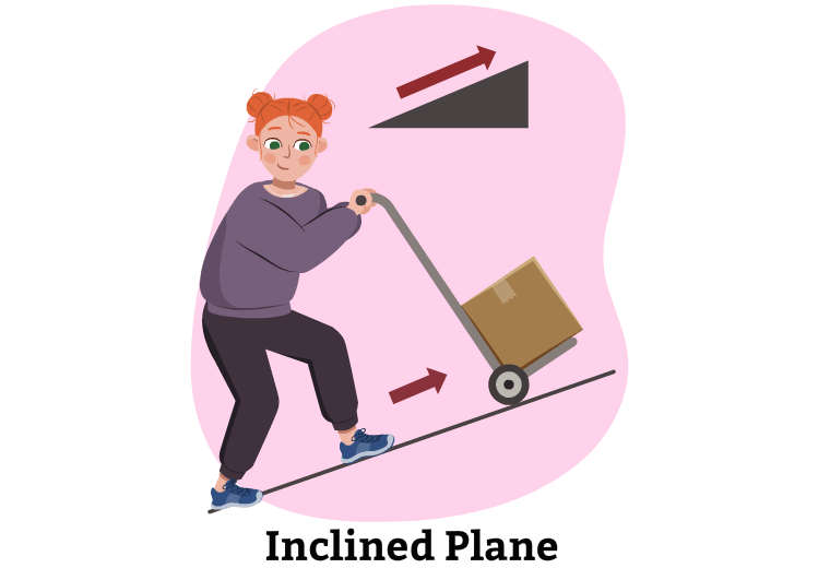
An inclined plane is a ramp that decreases the force that is needed to move an object. This means that less effort is needed if a load is transferred over a long ramp or inclined path, instead of lifting it directly over a vertical path. Some everyday examples of inclined planes are accessibility ramps, stairs, highways, and many more.
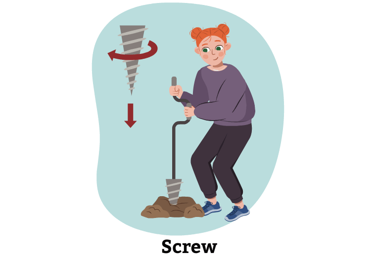
A screw is an inclined plane that is wrapped around a cylinder. Screws can be used for fastening and lifting. Some examples include screws that are used to fasten things together, a windmill, an auger, and many more.
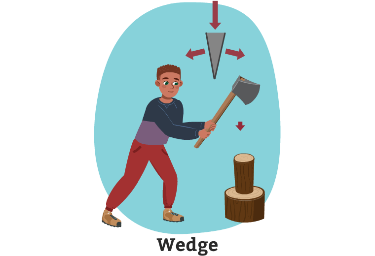
A wedge is two inclined planes put together that can be used to split things apart. For example, an axe, shovel, scissors, and many more.
The wedge is an axe. There is a child holding an axe and cutting wood. The force of moving the axe down into the wood moves the force down and outward from the wood.
A lever is a simple machine that has a rigid bar that can be turned freely about a fixed point. A lever has a fulcrum, which is a point or support around which the lever pivots. There are fixed and moveable fulcrums. A moveable fulcrum is a fulcrum which changes its position from one point to another. A teeter-totter, scissors, and a nutcracker are all examples of levers.

The lever is a long pole. A child is holding the pole. One end of the pole is underneath a big rock. The force of pushing down on the pole lifts the rock upwards.
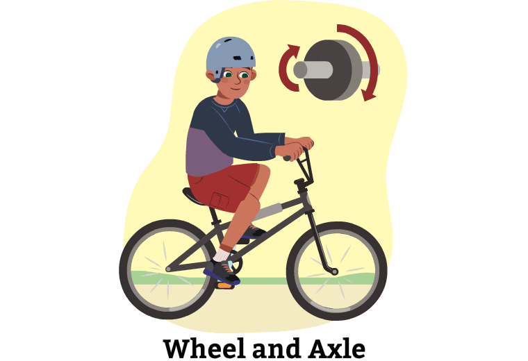
A wheel and axle is a wheel that is attached to a rod or stick. Engineers primarily use the wheel and axle to increase a turning or rotational force, rather than linear force (like a lever).
A pulley is a wheel with a groove for a rope. When something is attached to one end of the rope, it can be moved by pulling on the other end. Engineers consider pulleys when lifting heavy objects over a direct vertical path. To increase the pulley’s lifting power, pulley wheels are added to the pulley system so that the effort required to lift objects vertically is reduced.

There is a child holding one end of a rope that is moving through a pulley. At the end of the rope is a heavy weight. As the child pulls down on the rope, the weight is lifted up.
Pause and Reflect
Simple machines
What are some simple machines that you encounter in your life at school or in your community? Brainstorm a list in a method of your choice.
Mechanical advantage
Another component of simple machines is the mechanical advantage, which is the ratio of the output force to the input force. The formula is:
Mechanical advantage = input force ÷ output force
- output force: force exerted by a machine
- input force: force applied to a mechanism
Engineers use the mechanical advantage to decide which simple machine and what size would work best for specific task. For example, a crane uses a lever to lift heavy objects – an engineer would use the mechanical advantage to determine how long the lever arm should be and how much force will need to be applied.
The following chart identifies the inputs and outputs that are required to calculate the mechanical advantage of each simple machine. For example, if you are calculating the mechanical advantage of a wedge, you would divide the length (input) by the thickness (output).
Access the following Mechanical Advantage Guidelines to help you with the calculations in the next two sections of this learning activity.
|
Simple machine |
Input |
Output |
Picture example |
|---|---|---|---|
|
inclined plane |
slope length |
height |

|
|
wedge |
length |
thickness |

|
|
screw |
3.14 x diameter |
pitch |

|
|
lever |
effort arm |
resistance arm |

|
|
wheel and axle |
wheel radius |
axel radius |

|
Press the ‘Activity’ button to access the Mechanical Advantage Guidelines.
Before moving on to compound machines, check your understanding of the simple machines that you learned about in the previous section.
For each simple machine, select the corresponding description.
Compound machines
Compound machines are two or more simple machines that interact with one another to do work. Can you brainstorm any compound machines?
Record your ideas in a method of your choice.
Some of these machines can be very complex, and others are quite simple. For example, a door is a compound machine. It includes a lever (the hinges) and a wheel and axle (the knob).
A more complex example would be a bicycle.

What simple machines do you think are found in a bicycle?
Press ‘Answer’ to access a solution to this problem.
A bicycle has wheels and axles, levers, and pulleys.
The math behind it
Calculating work
Before you attempt to calculate work on your own, you can return to the video above for an example of how to calculate work.
The formula for work is:
Work = Force × Distance
[or W = F(d)]
Test your skills
Assume it takes 40N of force to carry a bowling ball from one end of a soccer field to the other. A soccer field is 120m long. How much work does a player do to move the bowling ball? Complete the calculation in a method of your choice and then check your answer.
Press ‘Answer’ to access a solution to this problem.
You will use the equation W = F(d) to solve this. You are given that:
F = 40N and that d = 20m. Substitute these into the equation.
W = F(d)
W = 40 × 20
W = 800J
Practice questions
Access the following document More Practice Questions to exercise your new skills.

When you are ready to check your work, press ‘Answers’ to access the answers to the above questions.
Answers to More Practice Questions
- 18,400J
- 900J
- 72J
- 700J
When both force and distance are unknown
What if you don’t know the force or distance? Let’s explore how to find these to help us calculate force. Follow along on the worksheet provided, or record your ideas on paper, digitally, or as an audio recording.
Access the following Worksheet for Calculating Work to follow along with the video experiment for trial 1 and trial 2.

Press the Activity button to access the Worksheet for Calculating Work.
Activity (Open PDF in a new tab)When you are ready to check your work. Access the following Answers to Worksheet for Calculating Work to check your understanding.

Press the Activity button to access the Answers to Worksheet for Calculating.
Activity (Open PDF in a new tab)Calculating mechanical advantage
In this section, you will be calculating mechanical advantage. Follow along with the experiment below, and if possible, create your own lever to calculate mechanical advantage. As you are exploring the video, complete the handout provided, or record your observations in another method of your choice.
Before moving forward, explore this video that outlines the scientific experimentation process.
Safety
Before you explore the following experiment, let’s perform a safety check.
Hands-on Science
Mechanical advantage experiment
This experiment is from Science North and explores mechanical advantage.
Complete the Lab Sheet: Mechanical Advantage in your notebook or using the following fillable and printable document. If you would like, you can use speech-to-text or audio recording tools to record your thoughts.

Press the Activity button to access the Lab Sheet: Mechanical Advantage.
Activity (Open PDF in a new tab)Press the following tabs to access the materials needed and experimental procedure for the Mechanical Advantage experiment.
If you do not have access to materials, access the “Video demonstration” tab to explore the experiment in action. You can use the video to make your observations and draw your conclusions.
- two rulers
- a pencil
- two plastic cups or containers (that are the same)
- tape
- small objects that can serve as weight (coins, buttons, Legos, marbles, etc.)
PART 1: Exploring distance advantage
- Use a ruler or paint stick to build a Class 1 lever. The ruler or paint stick is the beam and the pencil will be the fulcrum.
- Tape a cup to the beam (ruler or paint stick) where you want to place your load. Then put some of your weights into the cup.
-
 Compare the load distance to the
effort distance. In this experiment, the effort is the distance
that will be pushed down when you apply the effort and the load
distance is how far off the table the lever (the portion with
the load) moves when you apply the effort. For example, for this
image, the effort distance is 6cm and the load distance is 3cm.
Compare the load distance to the
effort distance. In this experiment, the effort is the distance
that will be pushed down when you apply the effort and the load
distance is how far off the table the lever (the portion with
the load) moves when you apply the effort. For example, for this
image, the effort distance is 6cm and the load distance is 3cm.
- Move the fulcrum to a slightly different place and then repeat step 3 two more times. Record your measurements.
- Calculate the distance ratio of the lever. This is the effort distance compared to the load difference. (the example above would be 6:3, simplified to 3:1)
- Repeat steps 1-4 for Class 2 and Class 3 levers. For these, you will need to measure the effort distance and load distance after applying the effort. For the Class 2 levers, be careful not to lift the load so far that the beam lifts off the fulcrum. For Class 3 levers, you might find it helpful to get a sibling or parent to hold the beam down on the fulcrum while you lift.
- Notice which levers provided a distance advantage, which means that the load distance is greater than the effort distance).
Part 2: Exploring force advantage
- Build a Class 1 lever like you did in Part 1, but tape one cup to each end of the beam this time.
- Add a set amount of small weights to the load side of the lever (possibly coins or beans). This is the load that is going to be lifted by the lever.
- Using the cup on the other side of the lever, continue to add small amounts of weight until the load is lifted. This weight is the effort weight. You can use the distance ratio to help predict what the effort weight will be. This is the opposite of the distance ratio. If the distance ratio of a lever is 3:1, then the force ratio will be 1:3.
- Compare how much weight (how many coins or beans) you have to add to the cup on the effort arm of the beam to get the load to move. Repeat this 3 times while moving the fulcrum slightly each time.
- Take note of how the placement of the fulcrum impacts how much weight, or effort, you have to apply to lift the load. Also take note if your predictions were correct. If they were not, why not?
Check out this video to explore a demonstration of the Mechanical Advantage experiment.
Please note that materials and procedure in the video may vary slightly from what is listed in the previous tabs.
Press ‘Things to Consider’ to access other things you might want to consider as you explore this experiment.
As observed from the experiments, not all levers provide the same type of mechanical advantage. Some provide a distance advantage, while some provide a force advantage. Therefore, we choose different kinds of levers for different tasks.
In part 2 of the experiment, did you notice that the closer to the load your fulcrum was located, the less weight (less effort) you had to apply to lift the load? This is because the amount of force applied to the effort side of the lever is equal to the amount of force that then acts on the load side. The bigger the distance from the fulcrum to the load, the bigger area that the force (effort) has to be spread across.
This, in turn, means that you have to apply more force (effort) to the effort side of the lever to reach the tipping point.
In part 2 of the experiment, were your predictions for the effort weight accurate? If the actual effort weight differed from your predictions, it is likely because your measurements are not exact. For example, if your weights were buttons that are almost the same size, but not quite, or that are made out of different kinds of materials, then the 5 buttons that make up your load might not weigh the same as the 5 buttons you add as your effort. The closer to identical all your weights are, the more accurate your predictions will be!
Consolidation
Show what you know!

Choose one or two of the following activities and complete them in a method of your choice.
Expert engineer
Design your own machine that helps people do work more easily. Be sure to include what materials you would use to build your machine, how it works, and how it makes work easier.
Create a review package
Create your own review package for simple and compound machines, as well as mechanical advantage. Your review package could include multiple choice, true or false, and short answer questions, and their answers.
Interactive notebook
Create an interactive notebook or flipbook that identifies and explains simple machines, compound machines, force and distance. Be sure to include specific examples!
Board game
Design a board game about simple machines, compound machines, and mechanical advantage. Your board game must include at least 20 question cards (with correct answers on the back).
Journal entry
Create a journal entry (writing, audio recording, or digitally) that details how you use simple and compound machines in your daily life. Be sure to include how the machines make work easier for people.
Any other ideas?
Have another idea to showcase your learning? Share your knowledge in another method of your choice. Be sure to include information about simple and compound machines, and mechanical advantage.
Reflection
As you read the following descriptions, select the one that best describes your current understanding of the learning in this activity. Press the corresponding button once you have made your choice.
I feel…
Now, expand on your ideas by recording your thoughts using a voice recorder, speech-to-text, or writing tool.
When you review your notes on this learning activity later, reflect on whether you would select a different description based on your further review of the material in this learning activity.